>Home>Compiling Rust for Cortex M3
Compiling Rust for Cortex M3
Published 9/4/2017
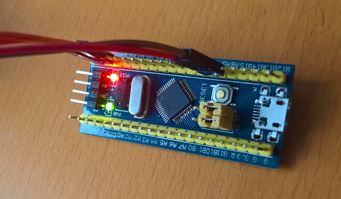
I was trying to get Rust to work on ARM based on the instructions found at http://www.acrawford.com/2017/03/09/rust-on-the-cortex-m3.html. Another good resource to look at is http://wiki.osdev.org/Raspberry_Pi_Bare_Bones_Rust. The goal is to be able to use rust on the mini STM32F103C8T6 development boards, which are cheap but make use of a powerful microcontroller. Here is another short summary of what is required.
Setup:
The first step is to install rust and set up nightly build (the nightly will apparently probably still be necessary till the end of 2017). Furthermore xargo is needed, which can be installed from the rust cargo repository.
curl https://sh.rustup.rs -sSf | shrustup update nightlyrustup default nightlyrustup component add rust-srccargo intsall xargo
Install the gcc ARM linker:
apt-get install gcc-arm-none-eab
Now create a new project:
cargo init --bin myproject
The Cargo.toml file:
[package]name = "arm-test"version = "0.1.0"
[dependencies]
[profile.dev]lto = true
[profile.release]lto = true
Make the directory ".cargo" and then create the file .cargo/config:
[build]target = "thumbv7m-none-eabi"
[target.thumbv7m-none-eabi]rustflags = [ "-C", "link-arg=-nostartfiles", "-C", "link-arg=-Tlayout.ld",]
We start by editing the file src/main.rs.
For our example we will need to refer to some registers. To do this we define two structs, PortRegisters and RCCRegisters, which refer to a set of consecutive registers that start at a location. We can make use of type aliases to tell the compiler that our registers have the type u32. Having a struct is useful, because if you look at the datasheet the same format of registers repeats itself. We can then just define two pointers for PORT_C and RCC which tell the compiler there is a struct of registers at the given address.
type Register = u32;

// Port Registers
struct PortRegisters { // 0x00: Control register lower crl : Register,
// 0x04: Control register higher crh: Register,
// 0x08: Input data register idr: Register,
// 0x0c: Output data register odr: Register,
// 0x10: Bit set / reset register bsrr: Register,}
// Reset and Clock Controlstruct RCCRegisters { // 0x00: Clock control register cr: Register,
// 0x04: Clock configuration register cfgr: Register,
// 0x08: Clock interrupt register cir: Register,
// 0x0C: peripheral reset register apb2_rstr: Register,
// 0x10: peripheral reset register apb1_rstr: Register,
// 0x14: peripheral clock enable register ahb_enr: Register,
// 0x18: peripheral clock enable register apb2_enr: Register,
}
const RCC: *mut RCCRegisters = 0x40021000 as *mut RCCRegisters;const PORT_C: *mut PortRegisters = 0x40011000 as *mut PortRegisters;
Next we define the main function, which does three things. First it enables the clock for the PORT C peripheral. This is done by writing to the APB2 ENR register of RCC. After that it sets the pin C13 to an output, and sets the output value for the entire PORTC to 0 (keep in mind the other pins are floating). We mark this function as naked, because there is no stack yet.
#[naked]fn main() { unsafe { // enable clock for PORTC (*RCC).apb2_enr = (1 << 4); // set port C13 to output (*PORT_C).crh= 0x44344444; // set output data registor to 0 (*PORT_C).odr = 0; }
loop {}}
We can then define the interrupts function. We want all other interrupts to simply stop the microcontroller in a loop.
#[naked]fn interrupts() { loop {}}
If we look at the default / sample application which was downloaded off the newly bought STM device, we can see that the binary of the file starts with the value 0x20000400, which is the default stack pointer location. After that it contains the address 0x80000145, which defines the memory address referring to the first instruction in flash. The further 32 bit words contain the entry points for interrupts. Note that the flash is mapped into memory twice, once at 0x08000000 and again at 0x00000000. This is why our code works, even though as you may see the memory addresses for the entry point differ between our sample and the app we generate. This file is normally located at 0x0800000 in memory.
Offset(h) 00 01 02 03 04 05 06 07 08 09 0A 0B 0C 0D 0E 0F
00000000  00 04 00 20 45 01 00 08 E7 02 00 08 DF 02 00 08  ... E...ç...ß...
00000010  E3 02 00 08 8D 01 00 08 5D 04 00 08 00 00 00 00  ã.......].......
00000020  00 00 00 00 00 00 00 00 00 00 00 00 0D 03 00 08  ................
00000030  91 01 00 08 00 00 00 00 E9 02 00 08 F9 03 00 08  ‘.......é...ù...
00000040  5F 01 00 08 5F 01 00 08 5F 01 00 08 5F 01 00 08  _..._..._..._...
00000050  5F 01 00 08 5F 01 00 08 5F 01 00 08 5F 01 00 08  _..._..._..._...
00000060  5F 01 00 08 5F 01 00 08 5F 01 00 08 5F 01 00 08  _..._..._..._...
00000070  5F 01 00 08 5F 01 00 08 5F 01 00 08 5F 01 00 08  _..._..._..._...
00000080  5F 01 00 08 5F 01 00 08 5F 01 00 08 5F 01 00 08  _..._..._..._...
00000090  5F 01 00 08 5F 01 00 08 5F 01 00 08 5F 01 00 08  _..._..._..._...
000000A0  5F 01 00 08 5F 01 00 08 5F 01 00 08 5F 01 00 08  _..._..._..._...
000000B0  5F 01 00 08 5F 01 00 08 5F 01 00 08 5F 01 00 08  _..._..._..._...
000000C0  5F 01 00 08 5F 01 00 08 5F 01 00 08 5F 01 00 08  _..._..._..._...
000000D0  5F 01 00 08 5F 01 00 08 5F 01 00 08 5F 01 00 08  _..._..._..._...
000000E0  5F 01 00 08 5F 01 00 08 5F 01 00 08 5F 01 00 08  _..._..._..._...
000000F0  5F 01 00 08 5F 01 00 08 5F 01 00 08 5F 01 00 08  _..._..._..._...
00000100  5F 01 00 08 5F 01 00 08 5F 01 00 08 5F 01 00 08  _..._..._..._...
00000110  5F 01 00 08 5F 01 00 08 5F 01 00 08 5F 01 00 08  _..._..._..._...
00000120  5F 01 00 08 5F 01 00 08 5F 01 00 08 5F 01 00 08  _..._..._..._...
00000130  DF F8 0C D0 00 F0 18 F8 00 48 00 47 81 04 00 08  ßø.Ð.ð.ø.H.G....
00000140  00 04 00 20 06 48 80 47 06 48 00 47 FE E7 FE E7  ... .H€G.H.Gþçþç
00000150  FE E7 FE E7 FE E7 FE E7 FE E7 FE E7 FE E7 FE E7  þçþçþçþçþçþçþçþç
00000160  FD 03 00 08 31 01 00 08 06 4C 07 4D 06 E0 E0 68  ý...1....L.M.ààh
00000170  40 F0 01 03 94 E8 07 00 98 47 10 34 AC 42 F6 D3  @ð..”è..˜G.4¬BöÓ
00000180  FF F7 DA FF BC 04 00 08 CC 04 00 08 00 BF FE E7  ÿ÷Úÿ¼...Ì....¿þç
We can define this in rust using a structure which contains our interrupt vector table. We then define a static instance of this struct, and define the entrypoint to be the function main, while all of the other interrupts are set to a dummy interrupt which just loops. Note that the #[link_section] directive defines the section which we refer to later in the linker script. Also note the #[used] directive, this is very important for compiling for release, as otherwise everything is optimized away!type IVFunction = fn ();
struct IVTable { main: IVFunction, nmi_handler: IVFunction, hard_fault: IVFunction, bus_fault: IVFunction, usage_fault: IVFunction,}
#[link_section = ".ivtable"]
#[used]
static IVTABLE: IVTable = IVTable { main: main, nmi_handler: interrupts, hard_fault: interrupts, bus_fault: interrupts, usage_fault: interrupts};
At the beginnig of the rust file we need to remove the std library, declare that there isn't a main function and the features for assembler, language items, start and naked functions. Then we need to declare two dummy functions for panics and "eh_personality".
#![no_std]#![no_main]#![feature(asm, lang_items, start, naked_functions)]
#[lang = "panic_fmt"]pub extern fn rust_begin_unwind(_: ::core::fmt::Arguments, _: &'static str, _: u32) -> ! { loop {}}
#[lang = "eh_personality"]pub extern fn rust_eh_unwind_resume() {}
The compiler requires a linker script to know how to build the binary. We first declare the memory layout of our device and then we declare a a text section, which should first contain a long word with the stack address, which we calculate as the top of the RAM address and then it should contain the ivtable. We then skip forward to address 0xD8, and include the rest of the ".text" section there (our main program execution code, including the main method).
MEMORY{ FLASH (rx) : ORIGIN = 0x00000000, LENGTH = 64K RAM (rwx) : ORIGIN = 0x20000000, LENGTH = 20K}
SECTIONS{ /* Set stack top to end of RAM */ __StackTop = ORIGIN(RAM) + LENGTH(RAM);
.text : { LONG(__StackTop); KEEP(*(.ivtable));
. = 0xD8;
*(.text*) } > FLASH}
We can then build our application using the following commands:
xargo build
arm-none-eabi-objcopy -O binary target/thumbv7m-none-eabi/debug/<myproj> <myproj>.bin
If you wan't you can dissasemble it using the following command, which I recommend doing if you run into any bugs. The assembly output can be seen at http://files.rudi-horn.de/website/2017/09/arm-test-dump.txt.
arm-none-eabi-objdump -d target/thumbv7m-none-eabi/debug/<myproj>
I then flashed the .bin file to the microcontroller using the flash tool available at http://www.st.com/en/development-tools/flasher-stm32.html.
For the full source code: http://files.rudi-horn.de/website/2017/09/arm-test.tar.gz